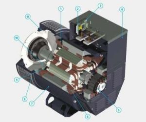
To generate electricity, a generator must not only have an alternator to pull it, but also have an alternator exciter . The field current is a direct current, which is applied to the rotor of the alternator to excite the magnetic field of rotor. So how to excite the alternator and what is alternator exciter circuit, today we will learn specifically about the alternator excitation with the content below.
Contents
What is a exciter armature?
The system is used to supply the required current to the rotor windings of a synchronous machine, this type of system is called an excitation system or alternator exciter TTTT. In other words, an excitation system is defined as a system used to generate magnetic flux by passing an electric current through a field winding. The main requirements of the excitation system are reliability under all service conditions, simple control, ease of maintenance, stability, and quick response.
The amount of exciter armature required depends on the load current, load power factor, and alternator speed. The excitation system is more necessary when the load current is large, the speed is smaller and the power factor of the system becomes hysterical.
An excitation system is a unit in which each alternator has an exciter in the form of a generator application. Centralized excitation systems have two or more busbar-level exciters. Centralized systems are very cheap, but failures in the system adversely affect the generators in the power plant.
Working principle of generator excitation
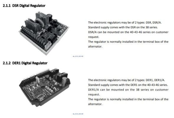
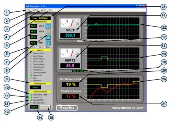
Depending on the type of source is rectified or the principle of static control of the circuit so that the user can easily distinguish. For example, for the Mecc Alte alternator, there are two types of pre-programmed excitation system control: Mecc Alte DSR / SR7 and Mecc Alte DER1 / UVR6
Types of alternator exciter circuit system
There are three types of alternator exciter circuit system:
- DC excitation system
- AC excitation system
- Rotor excitation system
- Brushless excitation system
- Static excitation system
DC excitation system
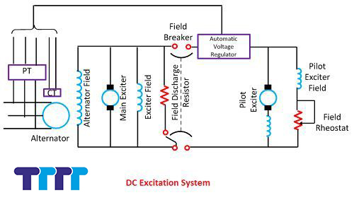 The DC excitation system has two exciters – the main exciter and the auxiliary exciter. The output of the exciter is regulated by an automatic voltage regulator (AVR) to control the output terminal voltage of the alternator. The AVR current transformer input ensures that the generator current is limited in the event of a fault.
When the field breaker is open, a field discharge resistor is connected across the field coil to dissipate the energy stored in the highly inductive winding.
The main and auxiliary exciters can be driven by the main shaft or by the motor separately. Direct-drive exciters are often preferred because they preserve the operating unit system and the exciter from being excited by external disturbances.
The voltage rating of the main exciter is about 400 V and its capacity is about 0.5% of the capacity of the alternator. Alternator exciter failures are quite frequent because of their high speed and because such a separate engine-controlled exciter is provided as a backup exciter.
AC generator exciter
The AC generator exciter system consists of an AC alternator and a thyristor rectifier bridge directly connected to the main AC generator. The main exciter can be self-excited or separately excited. AC excitation systems can be broadly classified into two categories which are explained in detail below:
Rotor generator exciter diagram system
Includes the rotation that is surrounded by the dashed line. The system consists of an AC exciter, a static field and a rotating armature. The output of the exciter is rectified by a full-wave thyristor bridge rectifier and fed to the field winding of the main AC alternator. Generator exciter diagram below:
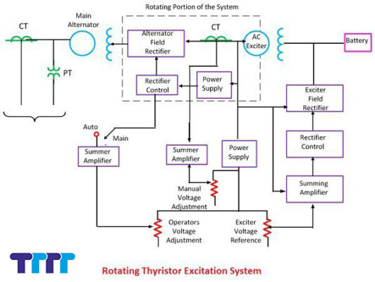
The field winding of the alternator is also provided through another rectifier circuit. The exciter voltage can be generated using its residual flux. The rectifier power supply and control generate a controlled trigger signal. The generator voltage signal is averaged and compared directly with the operator’s voltage adjustment in automatic operation. In manual operation mode, the excitation current of the alternator is compared with the separate manual voltage regulation.
Brushless excitation system
This system is shown in the figure below. The rotated part is surrounded by a dashed line rectangle. The brushless excitation system consists of an brushless alternator, rectifier, main exciter, permanent magnet alternator and generator diode. The main exciter and the exciter are driven by the main shaft. The main excitation machine has a stationary field and a rotating armature connected directly, via a silicon rectifier, to the field of the main generator.
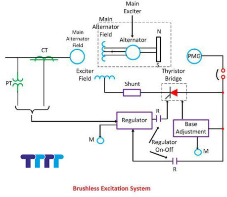
The pilot excitation machine is an axially-drive permanent magnet alternator with shaft-mounted rotating permanent magnets and a 3-phase stationary armature, providing the main exciter field through a silicon rectifier, in field of the main AC alternator. The pilot exciter is an axially driven permanent magnetic field generator with shaft-mounted rotating permanent magnets and a stationary 3-phase armature that supplies the main exciter through controlled thyristor bridges 3-phase full-wave control.
The system that eliminates the use of commutators, commutators and brushes has a constant short time and a response time of less than 0.1 second. The short time constant has the advantage of improving small-signal dynamic performance and facilitating the application of additional power system stabilization signals.
Reference: Low rpm alternator
Reference: Mecc Alte generator manual
Static alternator exciter wiring diagram system
In this system, the power supply is drawn from the generator itself via a 3 phases star or delta connected stepdown transformer. The primary of the transformer is connected to the busbar of the alternator, and their secondary provides power to the rectifier and also supplies power to the grid control circuit and other electrical equipment, alternator exciter wiring diagram below:
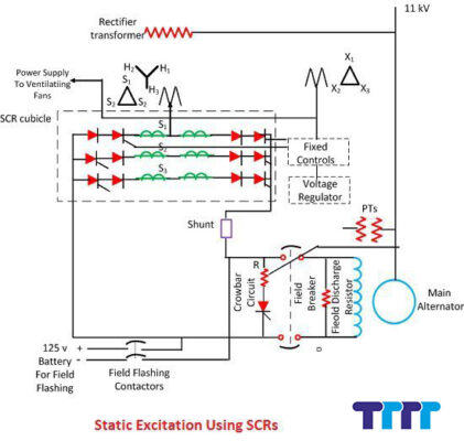
The alternator exciter wiring diagram has a very small response time and offers excellent dynamic performance. This system has reduced operating costs by eliminating exciter wind losses and winding maintenance.
TTTT GLOBAL co Ltd,.
Address: Landmark 4 Building, Vinhomes Central Park, 720A Dien Bien Phu Str, Ward 22, Binh Thanh District, Ho Chi Minh City, Vietnam.
Website: https://ttttglobal.com/en/
Email: Info@ttttglobal.com
Phone: 0286 2728 334
CATEGORY: MECC ALTE ALTERATOR DOCUMENTS
RELATED POST


 Tiếng Việt