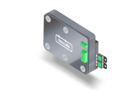
TTTT Global currently has user manual, installation and documentation to use for Sices genset controller ATSxxx/ DST46xx/ GCxxx/ MCxxx/ BTB200/ D-Monitor/ RNxxx/charge controller HSxxx series.
Contents
SICES HS315 charge controller parameter setting
When using the SICES HS315 charge controller, we need to install the BoardPrg4 software to set the parameters for the SICES HS315. BoardPrg4 is software that supports the installation of SICES controller lines.
BoardPrg4 is available on TTTT GLOBAL homepage: BoardPrg4- SICES
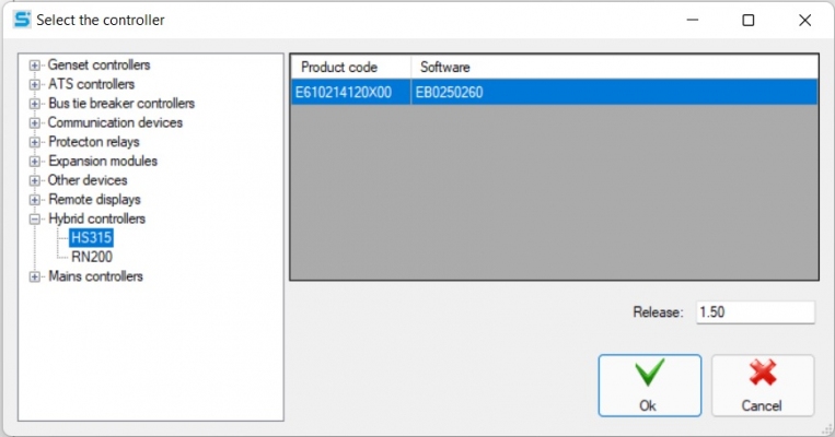
After installing and starting the software, we choose to set parameters for charge controller TTTT SICES HS315.
In the parameter setting section of the SICES HS315 charge control, there are many parameters to be set up, the main parameters include:
- System.
- Connection.
- Guard.
- Auxiliary function.
- Contact.
- Canbus.
System charge controller
Password protection
Configure password:
- Enter the manufacturer’s password.
- Enter the system password.
- Enter the user password.
- Enter passwords for commands using the serial ports.
Engine
- Enter the rated power of the motor.
- Fill in the rated speed of the motor when the frequency is 50Hz.
- Fill in the rated speed of the motor when the frequency is 60Hz.
- Enter the number of teeth of the flywheel.
- Fill in the Rpm/W ratio.
Generator
Select whether to use the governor to control the generator voltage (yes/no).
- Rated current of generator (A).
- Fill in the rated voltage (AC) of the generator (V)
- Fill in generator voltage (primary side) (V).
- Fill in the generator voltage (secondary side) (V).
Auxiliary source
- Fill in the rated voltage area (AC) of the auxiliary source (V).
- Fill in the auxiliary (primary side) voltage (V).
- Fill in the auxiliary power (secondary side) voltage (V).
Frequency
- Rated frequency (Hz).
Electric
Select the current sensor type.
- Fill ratio (A/V) for current 1.
- Fill ratio (A/V) for current 2.
- Fill ratio (A/V) for current 3.
- Fill ratio (A/V) for current 4.
Input / Output
Hardware configuration:
- Select function for terminal JG1.
- Select function for terminal JG2.
- Select function for terminal JG3.
- Select function for JG4 terminal.
- Select function for terminal JH1.
- Select function for terminal JH2.
- Select function for terminal JH3.
- Select function for terminal JH4.
- Select function for terminal JU1.
- The difference (+) for the JU1 terminal (mV).
- Fill in the difference (-) for terminal JU1 (mV).
- Fill in the gain value for terminal JU1.
- Select function for terminal JU2.
- Fill in the difference (+) for the JU2 terminal (mV).
- Fill in the difference (-) for the JU2 terminal (mV).
- Fill in the gain value for terminal JU2.
- Select function for terminal JU3.
- Fill in the difference (+) for the JU3 terminal (mV).
- Fill in the difference (-) for the JU3 terminal (mV).
- Fill in the gain value for terminal JU3.
- Select the function for the JU4 terminal.
- Fill in the difference (+) for the JU4 terminal (mV).
- Fill in the difference (-) for the JU4 terminal (mV).
- Enter the obtained value for the JU4 terminal.
- Select the function for the JQ terminal.
- Select the function for the JP terminal (yes/no).
Storage battery
- Fill in the rated voltage (VDC).
- Enter the value of the external DC/DC converter (primary) (VDC).
- Enter the value of the external (secondary) DC/DC converter (VDC).
- Fill in the power at rated discharge current (Ah).
- Fill in the rated discharge current (A).
- Fill in capacity at discharge current #2 (Ah).
- Fill in the current discharge value #2 (A).
- Enter Peukert’s constant.
- Select the battery model.
- Communication options for the battery.
- Select the number of batteries.
Connection charge controller
Secondary source
- Fill in the delay for sub-source measures (%).
- Enter the low frequency threshold of the sub source (%).
- Fill in the sub-source high frequency threshold (%).
- Enter the low voltage threshold of the auxiliary source (%).
- Enter the high voltage threshold of the auxiliary source (%).
- Fill in the sub-source presence delay time(s).
- Enter the auxiliary power delay fault time(s).
Parameters of running engine
- Fill in the motor stop threshold (rpm) (%).
- Fill in the engine starting threshold (rpm) (%).
- Enter the threshold of stopped motor (Vac) (%).
- Enter the engine starting threshold (Vac) (%).
- Fill in the stopped motor threshold (Hz) (%).
- Enter the motor starting threshold (Hz) (%).
- Fill in the stopped motor threshold (D +) (%).
- Enter the engine starting threshold (D +) (%).
- Select the motor to run from the oil pressure contact (yes/ no).
- Fill in the stopped motor threshold (Vdc) (%).
- Enter engine starting threshold (Vdc) (%).
Engine time
- Enter the duration of the preheat cycle (s).
- Enter the duration of the startup command(s).
- Enter the number of attempts to start(s).
- The delay between attempts starts.
- Enter the duration of the stop order (s).
- Enter the duration of the stopping cycle (s).
- Fill in the cooling cycle time(s).
- Enter the minimum temperature for the cooling cycle (oC).
- Fill in the time mask time to protect the motor(s).
- Fill in the maximum time for the operating condition(s).
- Fill in the delay time before delivering(s).
- Enter the minimum rated coolant temperature (oC).
- Fill in the idle speed cycle time(s).
- Fill in the time delay between the stop and fuel command(s).
- Enter the duration of the cleaning cycle(s).
- Enter the maximum time of the pre-lubrication cycle(s).
Other parameters for the sequence
- Fill in the inhibitor activation delay time(s).
- Enter the inhibitor deactivation delay time(s).
- Enter contactor holding time(s).
- Select generator power on/off on TEST (yes/ no).
- Select on/off load supply when GCB cannot be turned on (yes/no)
- Select generator start on/off if battery is disconnected (yes/no)
- Select a mask to disable the “XCB not closed” warning.
- Sequence options.
Storage battery
Main parameters:
- Enter the standard number of charge cycles to perform a full charge cycle.
- Select charge condition monitoring mode (voltage only/power only/both).
- Fill in the voltage due to temperature compensation (mV/°C).
- Fill in the current compensation due to temperature (C/h°C).
- Enter the discharge limit (C).
- Fill in the voltage to detect the end of discharge (%).
- Enter the delay time before starting the generator(s).
- Fill in the voltage connection window (%).
- Enter the maximum duration to match the voltage(s).
- Enter Ramp for current regulation (%/s).
- Fill gain for the current specified loop.
- Fill in the integration factor for the current regulation loop (1/s).
- Fill ramp to adjust voltage (%/s).
- Fill in the gain for the voltage regulator loop.
- Fill in the integration factor for the voltage regulator loop (1/s)
- Reselect voltage/speed regulator (Normal regulation/reverse regulation).
- Enter the minimum value for the voltage/speed regulator.
- Enter the maximum value for the voltage/speed regulator.
- Fill in the clearing rules.
Fully charged:
- Fill current (full) charge in BULK (C/h) mode.
- Enter the end-of-charge voltage (full) for BULK mode (%).
- Fill in the current (full) charge end for ABSORBTION (C/h) mode.
- Enter the maximum (full) charge time in ABSORBTION mode (h).
- Fill charge (full) voltage in FLOAT mode (%).
- Fill in the charging time (full) duration in FLOAT mode(s).
- Enter the billing deadline (in full) (C).
Standard fee:
- Fill charge (standard) current in BULK mode (C/h).
- Enter the charging end voltage (standard) for BULK mode (%).
- Enter the last (standard) charging current for ABSORBTION (C/h) mode.
- Enter the maximum charging time (standard) in ABSORBTION mode (h).
- Fill charging voltage (standard) in FLOAT mode (%).
- Enter the charging time (standard) in FLOAT mode (min).
- Enter the (standard) fee limit (C).
Sub LCB
Select the secondary LCBs activation map.
- Fill in the secondary LCB trigger delay time(s).
Variable speed motor
- Fill in the governor’s offset (%).
- Select speed adjustment mode.
- Fill in the fixed speed during rotation (rpm).
- Fill in the fixed speed delay time after rotation(s).
- Fill speed adjustable ramp (rpm).
- Enter the gain for the speed dial.
- Fill in the integration factor for the speed control loop (1/s).
Reference: Sices synchronizing controller
Reference: Generator protection relay
Guard charge controller
Generator protection
Frequency protection:
- Enter the minimum frequency threshold (%).
- Fill in the minimum frequency delay(s).
- Fill in the low frequency threshold (%).
- Fill low frequency delay(s).
- Fill in the high frequency threshold (%)
- Fill high frequency delay(s).
- Enter the maximum frequency threshold (%).
- Fill in the maximum frequency delay(s).
Voltage protection:
- Fill in the delay for the generator measure(s).
- Enter the minimum voltage threshold (%).
- Fill in the minimum voltage delay(s).
- Fill in the low voltage threshold (%).
- Fill low voltage delay(s).
- Fill in the high voltage threshold (%).
- Fill high voltage delay(s).
- Enter the maximum voltage threshold (%).
- Fill in the maximum voltage delay(s).
Current protection:
Fill generator delay line (%).
- Enter the generator high current threshold (%).
- Fill in the generator high current delay time(s).
- Enter the generator’s maximum current threshold (%).
- Fill in the generator maximum current delay time(s).
- Select generator maximum current action.
- Enter the generator short circuit threshold (%).
- Enter the generator short circuit delay time(s).
- Select generator short circuit action.
- Enter the generator reverse current threshold (%).
- Enter the time the generator reverses the delay current (s).
- Select upstream generator action.
Engine protection
Speed protection:
- Fill in the delay due to magnetization error(s).
- Select the action for the magnetization error.
- Enter the maximum speed threshold (frequency) (%).
- Fill in the maximum speed delay (frequency)(s).
- Fill in the maximum speed threshold (pick-up / w) (%).
- Crazy maximum speed delay (pick-up/w)(s).
Protection for coolant:
- Enter the low coolant temperature threshold (°C).
- Fill low coolant temperature delay(s).
- Enter the high coolant temperature threshold (°C).
- Fill in the high coolant temperature delay(s).
- Enter the maximum coolant temperature threshold (°C).
- Fill in the maximum coolant temperature delay(s).
Oil protection:
- Fill in the low oil pressure threshold (bar).
- Fill low oil pressure delay(s).
- Enter the minimum oil pressure threshold (bar).
- Fill in the minimum oil pressure delay(s).
- Enter the high oil temperature threshold (°C).
- Fill high oil temperature delay(s).
- Enter the maximum oil temperature threshold (°C).
- Fill in the maximum oil temperature delay(s).
Fuel protection:
- Enter the high fuel level threshold (%).
- Fill in the high fuel level delay(s).
- Enter low fuel level threshold (%).
- Fill low fuel level delay(s).
- Enter the minimum fuel level threshold (%).
- Fill in the minimum fuel level delay(s).
Battery protection:
- Fill in the belt break delay(s).
- Select the belt breaking action.
- Enter the battery low voltage threshold (%).
- Fill low battery voltage delay(s).
- Enter the battery high voltage threshold (%).
- Fill high battery voltage delay(s).
- Enter battery charging time for low voltage (min).
Power protection:
- Enter the maximum power threshold (%).
- Enter the maximum power delay(s).
- Select the maximum power action.
Other parameters for the motor:
- Fill in the emergency stop delay(s).
- Enter maintenance interval 1 (running hours) (h).
- Select action type for maintenance 1.
- Enter maintenance interval 2 (running hours) (h).
- Select action type for maintenance 2.
- Fill in the period of days for maintenance (days).
Storage battery protection
Temperature protection:
- Enter the battery temperature delay (°C).
- Enter the minimum battery temperature threshold (°C).
- Enter the minimum battery temperature delay(s).
- Enter the low battery temperature threshold (°C).
- Fill low battery temperature delay(s).
- Enter the high battery temperature threshold (°C).
- Fill in the high battery temperature delay(s).
- Enter the maximum battery temperature threshold (°C).
- Enter the maximum battery temperature delay(s).
Voltage protection:
- Enter the voltage delay of the battery (%).
- Enter the minimum battery voltage threshold (%).
- Fill in the minimum battery voltage delay(s).
- Enter the battery low voltage threshold (%).
- Fill low battery voltage delay(s).
- Enter the battery high voltage threshold (%).
- Fill high battery voltage delay(s).
- Enter the maximum voltage threshold of the battery (%).
- Fill in the maximum battery voltage delay(s).
Current protection:
- Enter the battery current delay (A).
- Fill in the high battery current threshold (A).
- Fill high pin line delay(s).
- Enter the maximum current threshold of the battery (A).
- Fill in the maximum battery current delay(s).
- Enter the battery short circuit threshold (A).
- Fill in the battery short circuit delay time(s).
Secondary power protection
Current protection:
- Fill in the auxiliary power from the current delay (A).
- Fill in the high auxiliary current threshold (A).
- Fill in the high auxiliary current delay(s).
- Enter the maximum auxiliary current threshold (A).
- Fill in the maximum auxiliary power current delay(s).
- Enter the auxiliary power short circuit threshold (A).
- Fill in the short circuit delay auxiliary source(s).
- Enter the auxiliary reverse current threshold (A).
- Fill in the reverse line delay auxiliary source(s).
Protection for loads
Voltage protection:
- Fill load delay voltage (%).
- Enter the minimum load voltage threshold (%).
- Fill in the minimum load voltage delay(s).
- Fill in the low load voltage threshold (%).
- Fill low load voltage delay(s).
- Fill in the high load voltage threshold (%).
- Fill load high delay voltage(s).
- Enter the maximum load voltage threshold (%).
- Fill in the maximum load voltage delay(s).
Current protection:
- Fill in the load from the current delay (A).
- Enter the high load current threshold (A).
- Fill in the high load line delay(s).
- Fill in the maximum load threshold current (A).
- Enter the maximum load current delay(s).
- Fill in the short circuit threshold load (A).
- Fill load short circuit delay(s).
- Fill in the load against the current threshold (A).
- Fill upstream load delay(s).
Auxiliary function charge controller
Plan
Plan the test:
- Select a test date.
- Enter the test start time.
- Enter the test duration (min).
Working day:
- Select the generator activation date.
- Fill in the generator enable start time.
- Enter the time the generator activates the dwell time.
Planning to start remotely:
- Select a remote start date.
- Enter the start time for remote boot.
- Fill in the dwell time for remote start.
Auxiliary function for the engine
Fuel pump:
- Select fuel pump mode.
- Select the fuel pump sensor type.
- Enter the starting threshold of the fuel pump (%).
- Enter the fuel pump stop threshold (%).
- Enter the maximum fuel pump activation time(s).
- Fill in the delay between the solenoid and the fuel pump(s).
- Select the power source for the fuel pump.
Preheat the coolant:
- Enter the coolant heating trigger threshold (°C).
- Enter the heating and cooling shutdown threshold (°C).
DPF reconstruction:
- Select DPF regeneration mode.
History Diary
Select the event to record.
- Fill in the same fast logging interval(s).
- Enter the same slow recording interval (m).
Device
Date and time:
- Select on/off daylight saving time.
- Enter daylight saving time offset (1 = 15 minutes, 4 = 1 hour).
- Enter timezone x4 (-47 … + 48) (1 = 15 minutes, 4 = 1 hour).
Display:
- Enter the delay time before turning off the light(s).
- Select light management when the engine is running.
- Select options for a single-line diagram.
- Keyboard options.
- Select mask to turn off pages
- Select mask to turn off pages WILL
- Select mask to turn off M pages
- Select mask to disable E . pages
Horn:
- Fill in the whistle duration(s).
Energy saving:
- Enter the battery low voltage threshold (VDC).
- Fill low battery voltage delay(s).
- Enter the accelerometer sensitivity threshold (0 = high / 127 = low).
- Fill in the number of events from the accelerometer.
At power on:
- Select the operation mode when power on.
Contact charge controller
Serial port 1
- Choose how to use the serial port (1).
- Enter the Modbus address (1).
- Select baud rate (1).
- Installation (1).
- Select the order of the Modbus registers (1).
Serial port 2
- Choose how to use the serial port (2).
- Enter the Modbus address (2).
- Select baud rate (2).
- Install (2).
- Select the order of the Modbus registers (2).
USB
- Enter the Modbus (USB) address.
- Fill in the order of the Modbus (USB) registers.
Modem
- Select the modem type.
- Select the event to alert.
- Enter the area name.
- #1 Phone number.
- #1 Type of phone number.
- #2 Phone number.
- #2 Type a phone number.
- #3 Phone number.
- #3 Type a phone number.
- #4 Phone number.
- #4 Type a phone number.
- Select dial mode.
- Enter the number of rounds.
- Enter the number of SMS messages.
- Enter the number of data calls.
Ethernet
- Enter the IP address.
- Fill in the subnet mask.
- Enter the network port.
- Fill Modbus/TCP port (0 = Modbus/TCP is disabled).
- Fill in the NTP server port (0 = NTP server is disabled).
- Fill in the NTP server address (0 = The NTP server is disabled).
- Fill in the primary DNS server.
- Fill in the secondary DNS server.
- Fill in the DHCP server port (0 = DHCP server is disabled).
- Fill in the DHCP server address (0 = DHCP server is disabled).
- Select the order of the Modbus (Ethernet) registers.
- Choose to enable/disable SNMP?
- Enter the SNMP manager’s address
- Fill in the SNMP message port (TRAP)
- Select SNMP notification events (TRAP)
Si.Mo.Ne
- Select activate and send data to Si.Mo.Ne.
- Fill in the main Si.Mo.Ne server – IP address or name.
- Enter the main Si.Mo.Ne server port.
- Fill in the secondary Si.Mo.Ne server – IP address or name.
- Fill in the secondary Si.Mo.Ne server port.
- Fill in the data sending interval if the engine is running(s).
- Fill in the data sending interval if the motor stops(s).
- Fill in Keep Alive Network – Data sending interval(s).
- Select a media event.
- Select voltage type.
GPS
- Select enable/disable GPS module.
- Fill in permanent coordinates – Latitude (symbol: + = North, – = South).
- Fill in permanent coordinates – Longitude (symbol: + = East, – = West).
- Enter the motion sensitivity to send the event (m).
- Fill in the time interval data sent to track(s).
Mobile phone network
- Select mobile network mode.
- Select the LTE category.
- Enter the primary APN (Access Point Name).
- Fill in the APN primary username (optional).
- Enter the APN master password (optional).
- Enter the Secondary APN (Access Point Name).
- Fill in the APN sub-user name (optional).
- Enter the APN sub-password (optional).
- Select the connection mode to the GPRS Network.
- Choose to enable Modbus/TCP.
- Select Modbus/TCP port.
CANBUS charge controller
Select engine controller
- Select the engine type.
- Select the Can-Bus command level.
- Selecting the Can-Bus warning disables the mask.
- Isochronous/draft selection for ECU.
- Select action on Can-Bus error.
- Enter the idle speed for the ECU (rpm).
- Fill in the maximum time there is no message from the engine(s).
- Enter speed at command 0% (rpm).
- Fill speed 100% command (rpm).
- Options for CanBus.
- Enter ID to transmit on Can-Bus.
Voltage regulator
- Select the voltage regulator type (AVR).
- Select the command level for the voltage regulator.
- Enter the transmission address for the voltage regulator.
- Fill in the voltage corresponding to 0% (VAC).
- Fill in the voltage corresponding to 100% (VAC).
- Enter the contact timeout with the AVR(s).
- Select the type of error handling that communicates with the AVR.
Installed on the system of charge controller SICES HS315
- JA: RS232 connection port.
- JB: USB connection port.
- JC: Ground GND.
- JD: Power supply:
- Pin 1: Positive source.
- Pin 2: GND.
- JE: Pins 1-4: Digital input.
- JG: Pins 1-4: Measuring head.
- JH: Pins 1-4: Measurement head.
- JI: Pins 1-6: Circuit breaker.
- JL: Pins 1-4: Motor command.
- JM: Pins 1-7: Analog input.
- JN: Pins 1-8: Configurable digital inputs.
- JO:
- Pins 1-3: RS485 serial.
- Pins 4-6: CANBUS ECU interface.
- JP: Pins 1-3: Measure battery temperature.
- JQ: Pin 1-2: Analog input 2.
- JR: Pins 1-2: Analog Output 1.
- JS: Ethernet connection port.
- JT:
- Pins 1-4: 9/12 digital input.
- Pins 5-8: 9/12 digital output.
- JU: Pins 1-8: Current Measures, GPS.
Operating the SICES HS315charge controller
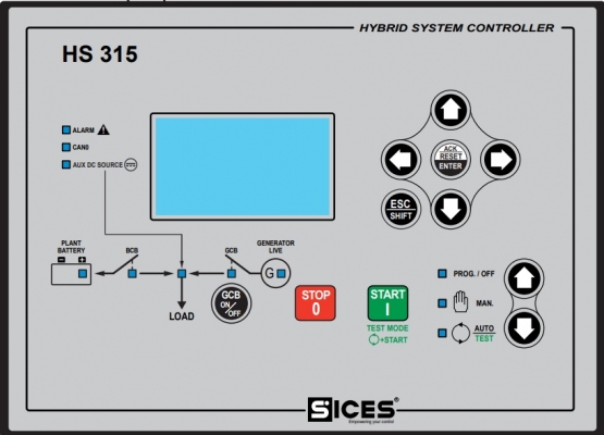
After setting parameters and installing on the generator, the next thing is to operate the machine. Commissioning is the final step to put into use. The operating steps are as follows:
- Check engine coolant.
- Check engine oil.
- Evenly pump fuel to the engine.
- Check the battery connector.
- Check the battery level on the system.
- Check generator input and other power.
- Power on the controller.
Manual start:
- Step 1: Select to manual mode.
- Step 2: Click Start to start the system.
- Step 3: Check the system parameters by the up, down, left, right buttons on the controller.
- Step 4: Check if the battery is enough for the system to work. If it is enough, turn on the load CB to operate, if it is not enough, turn on the GCB to let the generator charge the battery and provide temporary power to the load (if the generator source is not enough to supply the load and charge the battery, the backup power supply will not be sufficient). the other room will operate the load split).
- Step 5: If the battery is full, disconnect the GCB so that the battery can power the load without a generator.
- Step 6: If you want to stop the machine, turn off the load CB after it press Stop.
- Step 7: Power off the controller.
Auto start:
- Step 1: Select to Auto mode.
- Step 2: Check the system parameters by the up, down, left, right buttons on the controller.
- Step 3: Turn on CB load to work. The system will automatically calculate to use the battery and start the generator or auxiliary power.
- Step 4: If you want to stop the machine, turn off the load CB after it press Stop.
- Step 5: Power off the controller.
Application of HS315charge controller
The HS315 mixed source controller can be used in parallel between multiple sources and can both charge the battery and supply the load independently, so it is very suitable for applications on systems that use the main source of battery power. or battery. The charge controller HS315 provides protection for the battery or accumulator during use and optimizes battery life and battery life during operation to optimize resource use during operation.
The application of the power mix is very wide but typical and the most widely applied applications are in telecom, USP, light tower, etc.
Currently TTTT Global we have the charge control Sices HS315 including user manual and product documentation. Contact our TTTT Global now to learn more about the Sices HS315 power mix charge controller.
Company name:
TTTT GLOBAL co Ltd,.
Address: Landmark 4 Building, Vinhomes Central Park, 720A Dien Bien Phu Str, Ward 22, Binh Thanh District, Ho Chi Minh City, Vietnam.
Website: https://ttttglobal.com/en/
Hotline: +84286 2728 334
Email: Info@ttttglobal.com
CATEGORY: SICES DOCUMENTS
RELATED POSTS


 Tiếng Việt