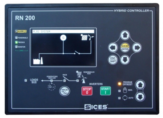
Sices D-PRO multifunction generator protection relay are used for additional generator protection in more demanding applications, such as medium or high voltage power plants, oil and gas installations. Corresponding to different applications, generator protection relay TTTT are also installed differently based on user needs. The D-Pro accessory is the product that maximizes protection with the Sices controller.
Contents
Sices D-Pro generator protection relay parameter setting
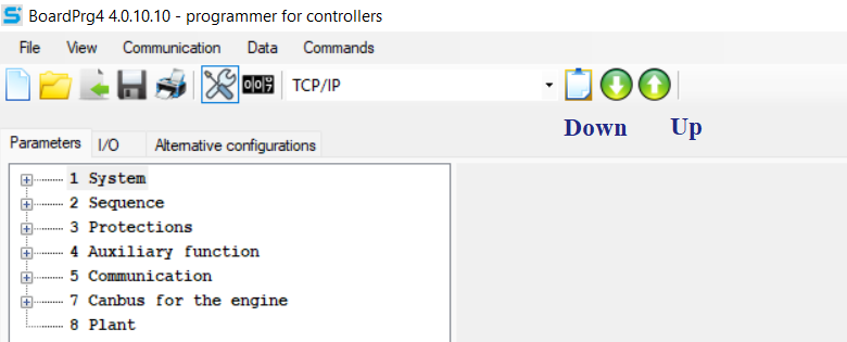
When using the Sices D-Pro generator protection relay, we need to install the BoardPrg4 software to set the parameters for the Sices D-Pro generator protection relay. BoardPrg4 is software that supports installation of SICES product lines.
BoardPrg4 is Scies software, available on TTTT GLOBAL homepage: Sices controller software download
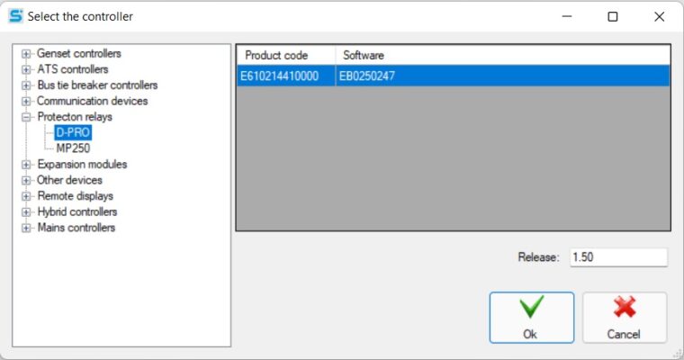
After installing and starting the software, we choose to set parameters for Sices D-Pro.
In the parameter setting section of D-Pro SICES controller , there are many parameters to be set, the parameters of the main generator protection relay include:
System.
Guard.
Functional Accessory.
Contact.
Canbus.
System
Password protection
Configure password:
- Enter the manufacturer password.
- Enter the system password.
- Enter the user password.
- Enter passwords for commands using the serial ports.
Generator
Select the phase number of the generator.
Fill in the generator’s rated voltage (V).
Enter the generator primary voltage (V).
Fill in the generator secondary voltage (V).
Enter the rated power of the generator (kW).
Select neutral of generator connected to the controller?
Select threshold for VLN.
Select the input voltage type for the generator.
Frequency
Fill in the frequency (Hz).
Electric
Enter the rated current for the generator (A).
Select enable filter on current measurement.
Fill in the primary current A (A).
Fill in the secondary current A (A).
Select current current A.
Fill in the primary current B (A).
Fill in the secondary current B (A).
Select current B.
Select transformer type for auxiliary current.
Primary current of auxiliary current (A).
Secondary current of auxiliary current (A).
Select the use of auxiliary current.
Select connection for auxiliary current.
Fill in the toroidal ratio for the auxiliary primary current (A).
Fill in the toroidal ratio for the secondary secondary current (A).
Choose the use of the toroidal current.
References: Automatic Transfer Switch
References: Generator auto transfer switch
Guard
Turn off protections
Select disable protection – Level 1.
Select disable protection – Level 2.
Select disable protection – Level 3.
Select disable protection – Level 4.
Select disable protection – Level 5.
Select disable protection – Level 6.
Select disable protection – Level 7.
Select disable protection – Level 8.
Output functions for protective measures
Select configure output protection – Level 1.
Select configure output protection – Level 2.
Select configure output protection – Level 3.
Select configure output protection – Level 4.
Select output type 01.
Fill in the delay for output 01(s).
Select output type 02.
Fill in the delay for output 02(s).
Select output type 03.
Fill in the delay for output 03(s).
Output type 04.
Fill in the delay for output 04(s).
Frequency protection
81U- Enter the minimum frequency threshold (%).
81U- Fill in the minimum frequency delay(s).
81O- Enter the maximum frequency threshold (%).
81O- Fill in the maximum frequency delay(s).
Voltage protection
27- Fill in the minimum voltage threshold (%).
27- Fill in the minimum voltage delay(s).
59- Fill in the maximum voltage threshold (%).
59- Fill in the maximum delay voltage(s).
27T- Select time protection.
27T- Fill in the minimum voltage threshold – protection time (%).
27T- Fill minimum voltage delay – protection time(s).
47- Select the required generator phase sequence.
47- Enter the delay for the required generator phase sequence(s).
59N- Enter the maximum residual voltage threshold (V).
59N- Fill in the maximum residual voltage delay(s).
Current protection
51- Select the peak current curve.
51- Enter the maximum current threshold (%).
51- Fill in the maximum line delay(s).
51N- Select the peak auxiliary/neutral current curve.
51N- Fill in the maximum sub/neutral threshold (%).
51N- Fill in the maximum auxiliary/neutral line delay(s).
51V- Select the peak current limiting voltage curve.
51V- Fill in the maximum current threshold voltage limit (%).
51V- Fill in maximum current delay Limit voltage(s).
50- Fill in the short circuit threshold (%).
50- Fill in the short circuit delay(s).
50N- Fill short-circuit current neutral threshold (%).
50N- Fill in the neutral short circuit delay current(s).
50V- Fill short circuit limit voltage threshold (%).
50V- Fill short circuit delay limit voltage(s).
46- Fill in the threshold I2 in negative order (%).
46- Fill in the negative order delay(s).
64- Fill in the limiting earth fault threshold / Maximum differential current (A).
64- Fill in limited earth fault delay / Maximum differential current(s).
Protection for differential current
Select allow 87G protection.
Enter the minimum current difference threshold (%).
Enter the maximum difference current threshold (%).
Enter the threshold for the second part of the start of the load current (%).
Fill in slope – first section (K1) (%).
Fill in slope – first section (K2) (%).
Fill in the maximum differential current delay(s).
Select for average measurement (87G).
Power protection
32P- Enter the maximum operating power threshold (%).
32P- Enter the maximum active power delay(s).
32Q-Fill in the maximum reactive power threshold (kVAr).
32Q-Fill in the maximum reactive power delay(s).
32RP- Enter the active power inversion threshold (%).
32RP- Enter the active power inversion threshold delay(s).
32RQ / 40- Enter the threshold of reactive power reversal / Loss of excitement (kVAr).
32RQ / 40- Fill in reactive power reverse delay / Excitement loss(s).
Battery protection
Enter the battery low voltage threshold (%).
Fill low battery voltage delay(s).
Enter the battery high voltage threshold (%).
Fill high battery voltage delay(s).
Functional Accessory
Equipment
Date and time:
- Choose daylight time.
- Select time zone.
Horn:
- Fill in the whistle time(s).
- Keyboard options.
History Diary
Select the log interval(s).
Enter the time period when logging is enabled(s).
Fill event location in archive before firing (%).
Select enable protections to activate first.
Contact
Serial port 1
Enter the Modbus address (1).
Select baud rate (1).
Select setting (1).
Select the order of the Modbus registers (1).
Serial port 2
Enter the Modbus address (2).
Select baud rate (2).
Select setting (2).
Select the order of the Modbus registers (2).
USB
Enter the Modbus (USB) address.
Select the order of the Modbus registers.
Ethernet
Fill in the domain name.
Enter the IP address.
Fill in the subnet.
Enter the network port.
Enter Modbus/ TCP port (0=Modbus/ TCP is disabled).
Enter the web server port (0= NTP server is disabled).
Select the order of the Modbus (Ethernet) registers.
Fill in the NTP server port (0 = NTP server is disabled).
Fill in the NTP server address (0 = The NTP server is disabled).
Fill in the primary DNS server.
Fill in the secondary DNS server.
Fill in the DHCP server port (0 = DHCP server is disabled).
Fill in the DHCP server address (0 = DHCP server is disabled).
Si.Mo.Ne
Select activate and send data to Si.Mo.Ne.
Select the main Si.Mo.Ne server – IP address or name.
Enter the main Si.Mo.Ne server port.
Select secondary Si.Mo.Ne server – IP address or name.
Fill in the secondary Si.Mo.Ne server port.
Fill in the data sending interval if the engine is running(s).
Fill in the data sending interval if the motor stops(s).
Keep Alive Network – Data sending interval (min).
Select a media event.
Select the voltage type of the generator.
GPS
Fill in permanent coordinates – Latitude (symbol: + = North, – = South).
Fill in permanent coordinates – Longitude (symbol: + = East, – = West).
CANBUS
Enter the EXBUS device address.
Sices D-Pro generator protection relay pinout
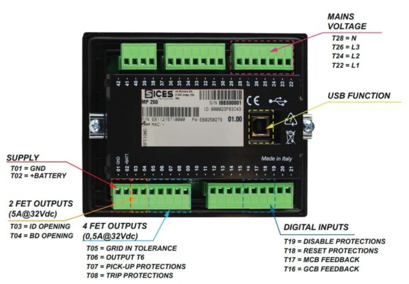
Sices D-Pro has a wide range of connections with 8 digital input ports, 4 digital output ports, 7 current measurement inputs for external current transformers, 1 current measurement input for transformers external, 1 pole bath three phase voltage sensor (L1-L2-L3-N), 1 max 100V voltage input for 59N protection, 8 LED indicator lights, 1 USB port, 1 serial port RS232 Modbus RTU, 1 RS485 Modbus RTU serial port, 1 RJ45 Modbus TCP Ethernet port, 1 CANBUS protocol.
JA: USB connection port
JB: Power supply pin.
JC: AUX TOROID.
JD: AUX CT.
JE: Current pin.
JL: Digital output pin.
JM: Programmable digital input pin.
JN: CANBUS.
JO: RS485 connection port.
JP: RS232 connection port.
JQ: Ethernet connection port.

If you need more information about generator control panel price or protection relay, please contact us:
TTTT GLOBAL co Ltd,.
Address: Landmark 4 Building, Vinhomes Central Park, 720A Dien Bien Phu Str, Ward 22, Binh Thanh District, Ho Chi Minh City, Vietnam.
Website: https://ttttglobal.com/en/
Hotline: +84286 2728 334
Email: Info@ttttglobal.com
CATEGORY: SICES DOCUMENTS
RELATED POSTS


 Tiếng Việt