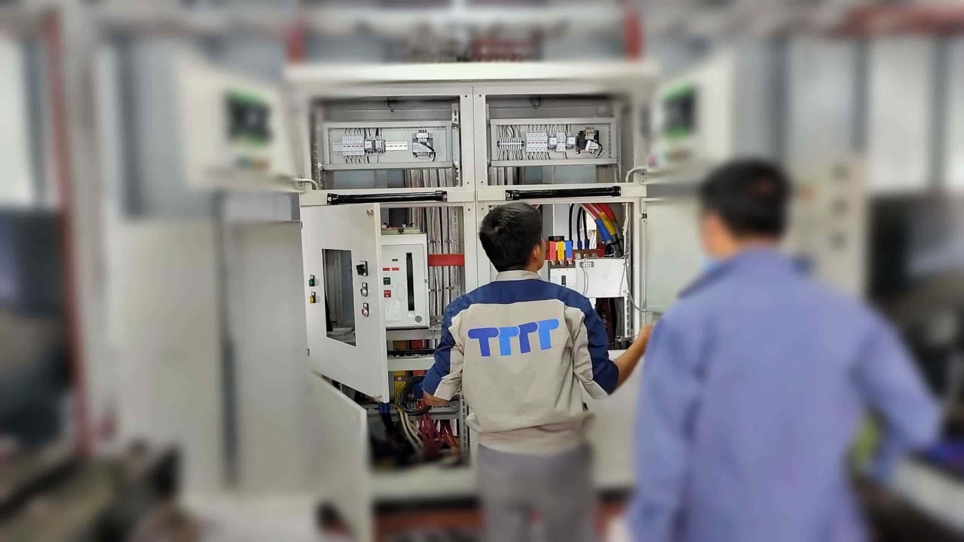
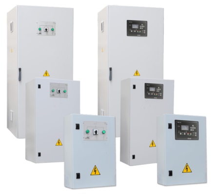
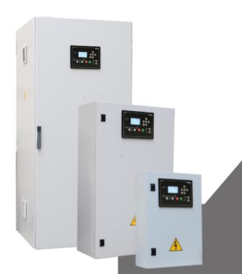
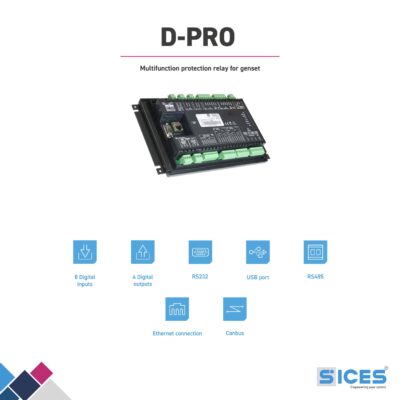
Automatic Transfer Switch is a system capable of automatically transferring power, the main function of the system is to transfer power from the mains to the generator and vice versa. This power transfer takes place when the mains power is lost due to breakdown or maintenance, when the mains power is back to normal, the system will switch from generator source to mains power.
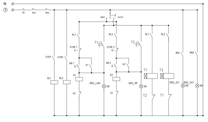
The system should have the automatic transfer switch diagram of the Automatic Transfer Switch TTTT including the dynamic circuit, the control circuit and the wiring diagram when used with the Sices ATS115 controller.
Contents
ATS diagram install instruction & Automatic transfer switch ATS structure
ATS electrical cabinets have many different automatic transfer switch diagram of different ATS cabinets, so the structure has a lot of different devices to bridge into an ATS switchboard system based on the functions and requirements of the user, the structure of automatic transfer switch ats:
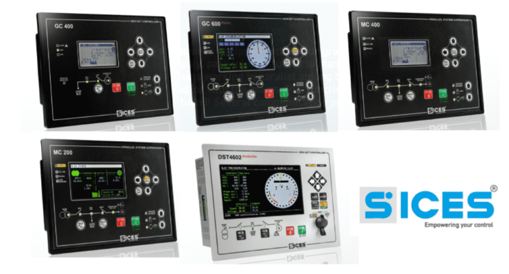
- ATS controller: Sices ATS115 automatic power transfer controller, Deepsea DSE335 automatic power transfer controller.
- Indicator lights: Generator indicator light, grid indicator light, load indicator light, headlight indicator light, etc.
- Control switch: Automatic mode, manual mode, switch to generator, switch to grid power.
- The protection and switching devices: CB, MCB, MCCB, ACB, Contactor, circuit breaker.
- Protection relays: current protection, voltage protection, frequency protection, load protection, etc.
Principle of 3-phase automatic switching
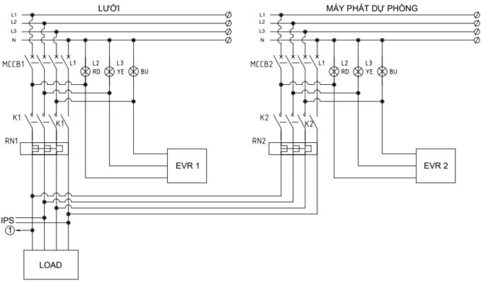
Principle of 3-phase automatic switching is to switch when the power is lost thanks to the circuit converter and the MCBs, contactors, and PLCs set up, the dedicated ATS power switch, the operating principle (principle diagram) of the ATS electrical cabinet is divided into two diagrams. The diagram is the schematic diagram of the dynamic circuit and the control circuit.
Motivational circuit of Automatic Transfer Switch
Control circuit of Automatic Transfer Switch
Advantages & disadvantages of Automatic Transfer Switch for generator
Advantages of Automatic Transfer Switch
- Generator auto transfer switch switchboard systems are often used for simple systems between a mains power source and a backup generator source.
- The system is compact, simple and easy to use, with built-in modern functions.
- Reasonable price.
- The system is highly customizable, with many different operating modes to choose from. Can connect to more advanced systems.
Disadvantages of Automatic Transfer Switch
- Usually only used in cases where there is a simple source, with a maximum current of 1600-3200A and a short-circuit withstand current that is not high.
- If it is intended for complex systems that often have multiple mains and backup power sources, an easy-to-handle ATS controller suitable for the system is required.
- If used for a complex system, it will take up a lot of space and the cost will be higher based on demand.
Reference: Generator control panel wiring diagram
Reference: Generator synchronization
Automatic transfer switch wiring diagram
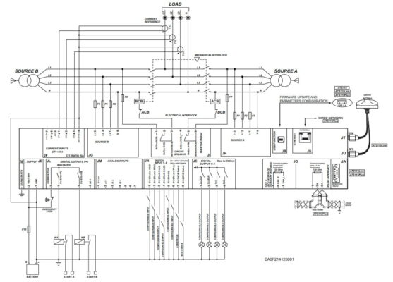
Components needed for the ATS switchboard system using the Sices ATS115 automatic power transfer controller:
- Electricity line.
- Generator source.
- Controller source.
- Lights.
- Measuring devices.
- The switches.
- Protection relays.
- Other minor ingredients….
When using the Sices ATS115 automatic power transfer controller, it will provide a lot of the most modern and convenient features today to best operate and protect your entire power transfer system.
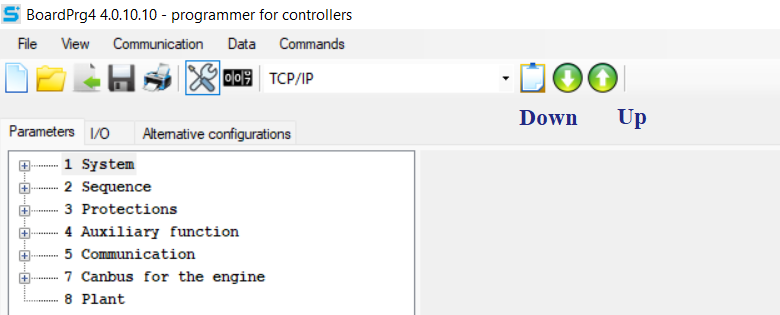
The Sices ATS115’s automatic power switch can also be ordered thanks to the BoardPrg4- SICES software, which enables us to set up all the system’s functions through such as:
- System
- Safety.
- Source A.
- Source B.
- Frequency.
- Electric.
- Connection
- Guard
- System protection.
- Battery protection.
- Other protection functions.
- Functional Accessory
- Schedule.
- Calendar repository.
- Equipment.
- Contact
- Serial port 1.
- Serial port 2.
- USB.
- Moden.
- Ethernet.
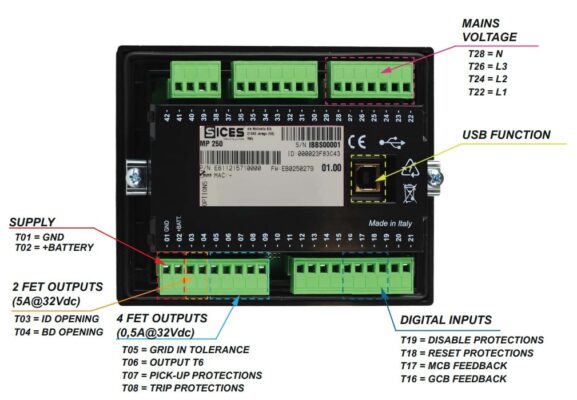
The controller, when connected to the system, has pins that connect to Automatic transfer switch wiring diagram and the Sices ATS115 controller:
- JA: RS232 connection port.
- JB: USB connection port.
- JC: Expensive connector.
- JD: Power supply:
- Pin 1: Positive source.
- Pin 2: GND.
- JE: Pins 1-4: Digital output.
- JF: Pins 1-7: Current input.
- JG: Pins 1-4: Source B.
- JH: Pins 1-4: Source A.
- JI: Circuit Breaker:
- Pins 1-3: GCB.
- Pins 4-6: MCB.
- JL: Pins 1-4: Motor command
- JM: Pins 1-7: Analog input.
- JN: Pins 1-8: Configurable digital inputs.
- JO: Connect
- Pins 1-3: RS485 serial.
- Pins 4-6: CANBUS ECU interface.
- JS: Ethernet connection port.
If you need more information about automatic transfer switch controller price or generator control panel price, please contact us:
TTTT GLOBAL co Ltd,.
Address: Landmark 4 Building, Vinhomes Central Park, 720A Dien Bien Phu Str, Ward 22, Binh Thanh District, Ho Chi Minh City, Vietnam.
Website: https://ttttglobal.com/en/
Hotline: +84286 2728 334
Email: Info@ttttglobal.com


 Tiếng Việt