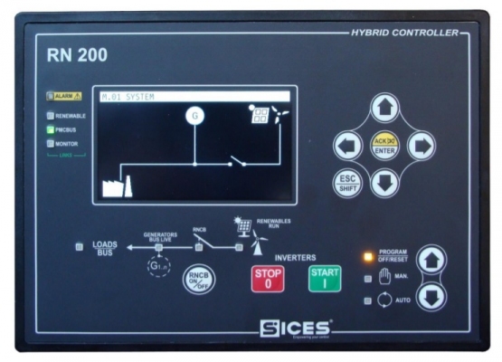
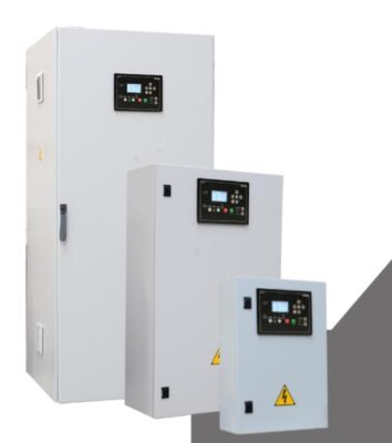
TTTT Global currently supplying Sices ATS controller, on TTTT Global there are instructions for user, installation and documentation to use for SICES ATSxxx/ DST46xx/ GCxxx/ MCxxx/ BTB200/ D-Monitor/ RNxxx/HSxxx series. You can refer to Sices ATS115 configuration.
Contents
Sices ATS115 controller parameter setting
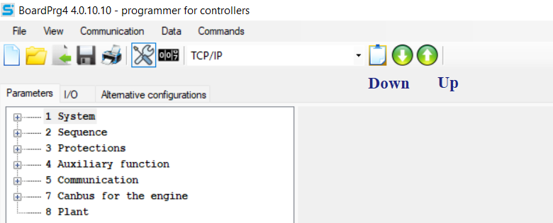
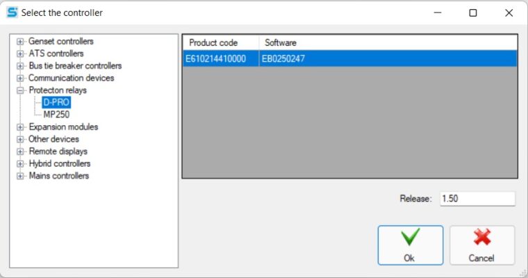
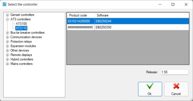
When using SICES ATS controller in general and SICES ATS115 in particular, we need to install BoardPrg4 software to set parameters for Sices ATS115 configuration. BoardPrg4 is the software that supports the installation of ATS controller lines.
BoardPrg4 is available to download on TTTT GLOBAL website: BoardPrg4- Sices
After installing and starting the software, we choose to set Sices ATS115 configuration TTTT.
In the parameter setting section of SICES ATS115, there are many parameters to be set, The main Sices ATS115 configuration includes::
- System.
- Connection.
- Guard.
- Functional Accessory.
- Contact.
System setting
Safety
Configure password:
- Enter the password for the manufacturer.
- Enter the password to install.
- Enter the password for the user.
- Enter the password for the commands from the gateway.
Source A
- Select source type A (mains/generators).
- Select the number of power phases A (1/3).
- Fill in the primary voltage source of source A (V).
- Fill in the auxiliary voltage source A (V).
- Enter the voltage present source threshold (V).
- Enter the frequency presence threshold (%).
- Enter the minimum frequency source threshold (%).
- Enter the maximum frequency source threshold (%).
- Enter the minimum voltage source threshold (%).
- Enter the maximum voltage source threshold (%).
- Fill in the source voltage asymmetry threshold (%).
- Select source phase sequence A.
- Fill in the time delay source presence(s).
- Fill in the absence source delay time(s).
- Fill in the source connection delay time(s).
- Enter the duration of the power-off cycle (s).
- Enter the delay time when the source stops(s).
- Select the neutral of the source connected to the board (yes/ no).
- Select thresholds on VLN (yes/no).
- Select allow test load acceptance (yes/ no).
- Select the input voltage type (1-100V/ 0-400V).
Source B
- Select source type B (mains/generator).
- Select the number of power phases B (1/3).
- Fill in the primary voltage source of source B (V).
- Fill in the auxiliary voltage source B (V).
- Enter the voltage present source threshold (V).
- Enter the frequency presence threshold (%).
- Enter the minimum frequency source threshold (%).
- Enter the maximum frequency source threshold (%).
- Enter the minimum voltage source threshold (%).
- Enter the maximum voltage source threshold (%).
- Fill in the source voltage asymmetry threshold (%).
- Select source phase sequence B.
- Fill in the time delay source presence(s).
- Fill in the absence source delay time(s).
- Fill in the source connection delay time(s).
- Enter the duration of the power-off cycle (s).
- Enter the delay time when the source stops(s).
- Select the neutral of the source connected to the board (yes/ no).
- Select thresholds on VLN (yes/no).
- Select allow test load acceptance (yes/ no).
- Select the input voltage type (1-100V/ 0-400V).
Frequency
- Enter the rated frequency (Hz).
Electric
- Enter the primary current of the system (A).
- Select the connection of the system currents (source A/source B/both).
- Enter the secondary current of the system (A).
- Fill in the system auxiliary primary current (A).
- Enter the secondary secondary current of the system (A).
- Select the connection of the system auxiliary current (source A / power B / both).
- Select the current connection backend (unused, shared, neutral).
Connection
- Select the ACB to be powered from the mains (yes/ no).
- Select the BCB to be powered from the mains (yes/ no).
- Enter the time the contactor exchange command(s).
- Enter the command time of the contactors(s).
- Choose to open ACB date (when ready / when power failure).
- Choose to open BCB date (when ready / when power failure).
- Fill in the delay time when opening ACB(s).
- Fill in the delay time when opening BCB(s).
- Network options.
- Sequence options.
Reference: Source protection
Reference: Protection relay
Protection setting
Current protective measures
- Enter the maximum auxiliary/neutral current threshold (A).
- Enter the maximum auxiliary/neutral current delay time (A).
- Enter the maximum current difference threshold (A).
- Fill in the maximum differential current delay time(s).
Battery protection
- Enter the battery low voltage threshold (%).
- Fill in the battery low voltage delay time(s).
- Enter the battery high voltage threshold (%).
- Fill in the battery high voltage delay time(s).
Other protective measures
- Fill in the inhibitory intervention delay time(s).
- Fill in the inhibitor release delay time(s).
- Fill in the emergency stop delay time(s).
Additional function setting
Schedule
Plan your test time:
- Select the source of the weekly check schedule source A.
- Enter the start time of the source test A.
- Enter power test time A (min).
- Select source weekly check schedule source B.
- Fill in the source test start time B.
- Enter power check time B (min).
Working day:
- Choose a weekly working time.
- Select the start time to work.
- Select the end time to work.
- Select the switching interval.
- Select the time when source A starts working.
- Select the time when source B starts working.
- Prioritize sources of the same type (none/source A/source B).
Start planning:
- Select the remote boot schedule.
- Select the remote boot start time.
- Select the remote boot end time.
Calendar storage
- Select the event to be saved.
- Select the interval for analog quick recording.
- Select the interval for analog slow recording.
Device
Enter date and time:
- Choose daylight saving time.
- Select daylight saving time.
- Select the local time zone.
Display:
- Enter the delay time before turning off the light(s).
- Keyboard options.
Alarm siren:
- Fill in the time of the siren.
Connection setting
Serial port 1
- Select the serial port type.
- Enter the modbus address.
- Select baud rate (Bps).
- Select bit setting.
- Select order of modbus registers.
Serial port 2
- Select the serial port type.
- Enter the modbus address.
- Select baud rate (Bps).
- Select bit setting.
- Select order of modbus registers.
USB
- Enter the USB address.
- Select the order of the Modbus USB register.
Modem
- Select the modem type.
- Select events to report.
- Enter phone number 1.
- Select a phone number type 1.
- Enter phone number 2.
- Select a phone number type 2.
- Enter phone number 3.
- Select phone number type 3.
- Enter phone number 4.
- Select a phone number type 4.
- Select call mode.
- Enter the number of rounds.
- Enter the number of SMS.
- Enter the number of data calls.
Ethernet
- Enter the IP address.
- Fill in the subnet mask.
- Enter the network port.
- Enter Modbus/TCP port.
- Fill in the web server port.
- Fill in the NTP server port.
- Enter the NTP server address.
- Fill in the primary DNS server.
- Fill in the secondary DNS server.
- Enter the DHCP server port.
- Fill in the DHCP server address.
Sices ATS115 installation on generator auto transfer switch with wiring diagram
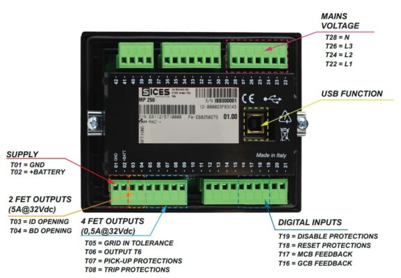
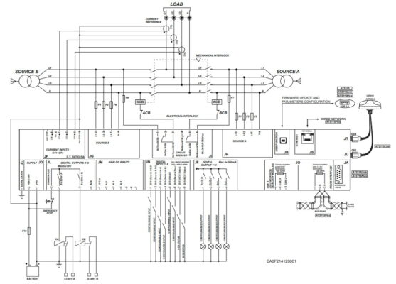
Below is a diagram of the floating connections and the wiring diagram of the Sices ATS115 controller used for the generator auto transfer switch unit. You can also learn more about the ATS cabinet schematic diagram for an in-depth understanding of the entire automatic power conversion system.
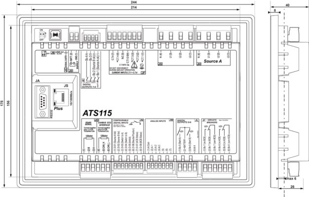
JA: RS232 connection port.
JB: USB connection port.
JC: Expensive connector.
JD: Power supply:
- Pin 1: GND.
- Pin 2: Positive source.
JE: Pins 1-4: Digital output.
JF: Pins 1-7: Current input.
JG: Pins 1-4: Source B.
JH: Pins 1-4: Source A.
JI: Circuit Breaker:
- Pins 1-3: GCB.
- Pins 4-6: MCB.
JL: Pins 1-4: Motor command
JM: Pins 1-7: Analog input.
JN: Pins 1-8: Configurable digital inputs.
JO: Connect
- Pins 1-3: RS485 serial.
- Pins 4-6: CANBUS ECU interface.
JS: Ethernet connection port.
Operating automatic transfer switch using SICES ATS115 controller
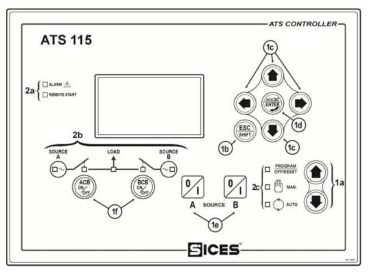
After setting parameters for the Sices ATS115 controller and installing it on the generator, the next thing is to operate the automatic transfer switch. Commissioning is the final step to put into use. The operating steps are as follows:
Check generator fuel.
Check generator engine coolant.
Check generator engine lubricating oil.
Evenly pump the fuel for the generator engine.
Check generator battery connector.
Manual start:
Step 1: Cut off the CB above the load.
Step 2: Turn on the controller power switch.
Step 3: Press select to manual mode.
Step 5: Use the up, down, left, right buttons to view system parameters.
Step 6: After the test is completed, turn on the CB supplying power to the load (buttons A and B can be used to switch to source A and source B; use ACB and BCB buttons to open and close the CB of the devices. sources A and B).
Step 7: If you want to stop the machine, cut off the CB above the load.
Step 8: Press to program/off/reset mode.
Auto start:
Step 1: Cut off the CB above the load.
Step 2: Turn on the controller power switch.
Step 3: Press select to auto mode.
Step 4: Check the parameters on the system.
Step 5: Turn on the CB to supply power to the load (the system will automatically operate if the grid power is lost, it will run the generator and if there is a grid source, the generator will be turned off).
If you need more information about generator control panel price, please contact us:
TTTT GLOBAL co Ltd,.
Address: Landmark 4 Building, Vinhomes Central Park, 720A Dien Bien Phu Str, Ward 22, Binh Thanh District, Ho Chi Minh City, Vietnam.
Website: https://ttttglobal.com/en/
Hotline: +84286 2728 334
Email: Info@ttttglobal.com
CATEGORY: SICES DOCUMENTS
RELATED POSTS


 Tiếng Việt