TTTT Global currently sells SICES controllers, on TTTT Global there are instructions for use, installation and documentation for use with Sices controller series ATSxxx/ DST46xx/ GCxxx/ MCxxx/ BTB200/ D-Monitor/ RNxxx/HSxxx.
Contents
SICES RN200 solar controller parameter setting
When using the SICES RN200 solar controller, we need to install the BoardPrg4 software to set the parameters for the SICES RN200. BoardPrg4 is software that supports the installation of SICES controller lines.
BoardPrg4 is available on TTTT GLOBAL homepage: BoardPrg4- SICES
After installing and starting the software, we choose to solar controller TTTT SICES RN200.
In the parameter setting section of the SICES RN200 solar controller, there are many parameters to be set, the main parameters include:
- System.
- Connection.
- Guard.
- Auxiliary function.
- Contact.
- PMCB.

System solar controller
Password protection
Configure password:
- Enter the password for the ‘console builder’ level.
- Enter the password for the ‘installer’ level.
- Enter the password for the ‘user’ level.
Busbar
- Select input type for busbar voltage (1 phase/3 phase).
- Select phase number of busbar voltage (1-100/ 0-400 VDC).
- Enter the rated voltage of the busbars (VAC).
- Fill in the busbar voltage transformer (primary side) (VAC).
- Fill in the busbar voltage transformer (secondary side) (VAC).
- Select the neutral of the busbars connected to the controller (yes/ no).
Renewable source
- Select input type for regenerative mains voltage (1 phase/3 phase).
- Select the phase number of the regenerative mains voltage (1-100/ 0-400 VDC).
- Enter the rated voltage of the regenerative sources (VAC).
- Fill in the regenerative power (primary side) voltage transformer (VAC).
- Fill in the regenerative source voltage transformer (secondary side) (VAC).
- Select whether neutral of the renewable sources connected to the controller (yes/ no).
Frequency
- Enter the rated frequency (Hz).
Electric
- Fill in the rated current (A).
- Select current transformer connection (On regenerative / On load).
- Fill in the current transformer (primary side) (A).
- Fill current transformer (secondary side) (A).
- Select transformer type for auxiliary current (Current/Toroidal).
- Select connection for auxiliary current (On regenerative / on load).
- Fill in the primary current of C.T. or toroidal ratio for auxiliary current (A).
- Fill in the secondary current of C.T. or toroidal for auxiliary current (A).
- Select the use of auxiliary current (Don’t use/share/use separately/measure power).
- Enter the correction value to calculate the power on the auxiliary line.
Overview
- Choose whether to use RNCB (Do not use / internally managed / externally managed).
- Fill in the delay before opening the minimum voltage coil (RNCB)(s).
Connection solar controller
Sensor for busbar
- Select sensor type (Internal sensor/External sensor).
- Fill in the delay for the measure (%).
- Enter the voltage presence threshold (%).
- Fill in the low frequency threshold (%).
- Fill in the high frequency threshold (%).
- Select whether to apply thresholds for phase voltage (yes/no).
- Fill in the low voltage threshold (%).
- Fill in the high voltage threshold (%).
- Fill in the voltage unbalance threshold (%).
- Select the required sequence of stages (Counter-clockwise/clockwise/zero).
- Select the delay time for “within tolerance”(s).
- Select the delay time because of the “out of tolerance”(s).
Active energy management
- Enter the minimum power for the generator (%).
- Enter the minimum power delay for the generator (%).
- Enter the trigger delay for the power limit on the drive(s).
- Fill in the disable delay due to power limit on the inverter(s).
- Fill in the load ramp for the inverter (%)
- Enter the rotation reserve for the island mode (%).
- Fill in the spinning reserve for parallel to the net (%).
Reactive power management
- Select reactive power management mode.
- Enter the generator power factor for the delay load.
- Enter power factor for generator for top load.
Other parameters for the sequence
- Fill in the trigger delay for the start inhibition for the drive(s).
- Enter the deactivation delay time for the start inhibition for the drive(s).
- Enter the maximum time to start the drive(s).
- Enter the maximum time to stop the drive(s).
- Select action when there is a generator with “GCB not on” (RNCB On / Containment / No).
- Sequence options.
Inverters for renewable sources
Overview:
- Inverter polling mode (Standard/Broadcast).
Inverter 01/02/03/04/05/06/07/08/09/10/11/12/13/14/15/16
- Select the inverter type.
- Fill in the rated operating power (kW).
- Enter the rated reactive power (kvar).
- Select the communication port.
- Enter the Modbus address.
- Enter the IP address or DNS name.
- Fill in the TCP port.
- Enter the maximum time for the answer (milliseconds).
- Enter the maximum number of attempts for each message.
Reference: 30a solar charge controller
Reference: Automatic Transfer Switch
Guard solar controller
Protecting renewable energy
Overview:
- Fill in the lag for renewable source measures (%).
- Select also applies thresholds for phase-to-neutral voltage (yes/no).
- Ton number:
- Fill in the minimum frequency threshold (81 <<) (%).
- Fill in the delay for the minimum frequency (81 <<)(s).
- Fill in the low frequency threshold (81 <) (%).
- Fill delay for low frequency (81 <)(s).
- Fill in the high frequency threshold (81>) (%).
- Fill in the delay for high frequency (81>)(s).
- Enter the maximum frequency threshold (81 >>) (%).
- Fill in the delay for the maximum frequency (81 >>)(s).
Voltage:
- Fill in the threshold for the minimum voltage (27 <<) (%).
- Fill in the delay for the minimum voltage (27 <<)(s).
- Fill low voltage threshold (27 <) (%).
- Fill in the delay for low voltage (27 <)(s).
- Fill in the threshold for high voltage (59>) (%).
- Fill in the delay for high voltage (59>)(s).
- Fill in the threshold for the maximum voltage (59 >>) (%).
- Fill in the delay for the maximum voltage (59 >>)(s).
- Fill in the voltage unbalance threshold (47) (%).
- Fill delay when voltage unbalance (47)(s).
Current protection:
- Enter threshold number 1 for maximum current (%).
- Fill in delay #1 for maximum current(s).
- Choose mode #1 for maximum current.
- Choose action #1 for maximum current.
- Enter threshold number 2 for maximum current (%).
- Fill in delay #2 for maximum current(s).
- Select mode #2 for maximum current.
- Choose action #2 for maximum current.
- Fill in the maximum auxiliary/neutral current threshold (Aac).
- Fill in the maximum auxiliary/neutral current delay(s).
- Power supply voltage protection
- Fill in the low power supply voltage threshold (%).
- Fill power supply low delay voltage(s).
- Fill in the high source voltage threshold (%).
- Fill power supply high voltage delay(s).
Other protective measures
- Enter the delay time for the emergency button(s).
Auxiliary function solar controller
Planning
Plan your working time:
- Choose a weekly schedule.
- Enter the job start time.
- Enter stop time.
- Planning a REMOTE START:
- Choose a weekly REMOTE START schedule.
- Enter the “REMOTE START” start time.
- Enter the “REMOTE START” dwell time.
History Diary
- Select the event to record.
- Fill in the registration period (inverter in power supply)(s).
- Enter the registration period (drive stopped)(s).
Device
Data – time:
- Select daylight saving time on/off (yes/ no).
- Enter daylight saving time offset (1 = 15 minutes, 4 = 1 hour).
- Enter timezone x4 (-47 … + 48) (1 = 15 minutes, 4 = 1 hour).
Display
- Enter the delay time before turning off the light(s).
- Select lamp management with inverter in power supply (normal/always).
- Select options for a single-line diagram.
- Select keyboard/display options.
- Fill in the brightness of the LED.
- Fill in the screen profile.
Horn
- Fill in the whistle duration(s).
Temperature
- Fill in the high table temperature threshold (oC).
Contact solar controller
Serial port 1
- Choose how to use the serial port (1).
- Enter the Modbus address (1).
- Enter baud rate (1) (Bps).
- Select setting (1).
- Select the order of the Modbus registers (1).
- Fill in the delay between messages (1) (ms).
Serial port 2
- Choose how to use the serial port (2).
- Enter the Modbus address (2).
- Enter baud rate (2) (Bps).
- Select setting (2).
- Select the order of the Modbus registers (2).
- Fill in the delay between messages (2) (ms).
USB
- Enter the Modbus (USB) address.
- Select the order of the Modbus (USB) registers.
Modem
- Select the event to alert.
- Fill in the domain name.
- #1 Phone number.
- #1 Type of phone number.
- #2 Phone number.
- #2 Type a phone number.
- #3 Phone number.
- #3 Type a phone number.
- #4 Phone number.
- #4 Type a phone number.
- Select dial mode.
- Enter the number of rounds.
- Enter the number of SMS messages.
- Enter the number of data calls.
Ethernet
- Enter the IP address.
- Enter the subnet mask.
- Enter the network port.
- Fill Modbus/TCP port (0 = Modbus/TCP is disabled).
- Fill in the web server port (0 = Web server is disabled).
- Fill in the NTP server port (0 = NTP server is disabled).
- Fill in the NTP server address (0 = The NTP server is disabled).
- Fill in the primary DNS server.
- Fill in the secondary DNS server.
- Fill in the DHCP server address (0 = DHCP server is disabled).
- Fill in the DHCP server port (0 = DHCP server is disabled).
- Bear the order of the Modbus (Ethernet) registers.
GPS
- Fill in permanent coordinates – Latitude (symbol: + = North, – = South).
- Fill in permanent coordinates – Longitude (symbol: + = East, – = West).
PMCB
- Electrical address of the controller for PMCB.
Installation on the system of solar controller SICES RN200
- JA: RS232 connection port.
- JB: Ground.
- JC: Power supply:
- Pin 1: GND.
- Pin 2: Positive source
- JD: Pins 1-4: Digital input 1-4.
- JE: Pins 1-6: Current input C.T.1-C.T.3.
- JF: Pins 1-4: Generator source voltage.
- JG: Pins 1-4: Regenerative source voltage.
- JH: Pins 1-6: Digital output.
- JI: Pin 1-2: C.T.4 current input.
- JJ: Pins 1-4: Digital output 15-16 and analog input 7.
- JK: Pins 1-9: Analog input 3-6.
- JL: Pins 1-8: Digital input 1-8.
- JM: CANBUS connection port 0.
- JNA: USB A port.
- JNB: USB B port.
- JO: Pins 1-6: Digital input 14-18.
- JP: Pins 1-6: Digital input 9-13.
- JQ: Pins 1-5: Digital output 10-14.
- JR: Pins 1-5: Digital output 5-9.
- JS: Pins 1-3: Analog output 2.
- JT: Pins 1-3: Analog output 1.
- JU: Pins 1-6: Analog input 1-2.
- JW: RS485 connection port.
- JX: CANBUS B connector.
- JY: Ethernet connection port.
Operating the SICES RN200 solar controller
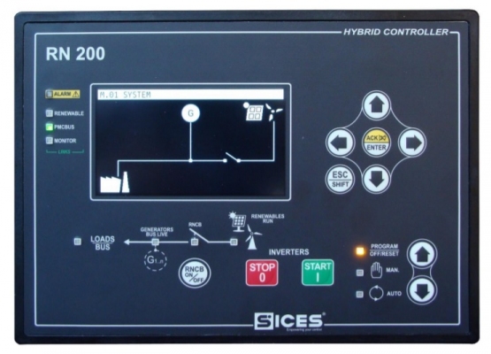
After setting parameters and installing on the generator, the next thing is to operate the machine. Commissioning is the final step to put into use. The operating steps are as follows:
- Check engine coolant.
- Check engine oil.
- Evenly pump fuel to the engine.
- Check the battery connector.
- Check the battery level on the system.
- Check regenerative power input and generator power.
- Power on the controller.
Manual start:
- Step 1: Select to manual mode.
- Step 2: Click Start to start the system.
- Step 3: Check the system parameters by the up, down, left, right buttons on the controller.
- Step 4: Check if the amount of power is enough for the load. If not enough then turn on the RNCB to add a renewable energy source to power the active load.
- Step 5: If the amount of energy is enough to supply the load, turn on the load CB to make the load work.
- Step 6: If you want to stop, turn off the load CB, then turn off the RNCB and then press Stop.
- Step 7: Power off the controller.
Auto start:
- Step 1: Select to Auto mode.
- Step 2: Check the system parameters by the up, down, left, right buttons on the controller.
- Step 3: Turn on CB load to work. The system will automatically calculate to turn on/off the RNCB to operate the load with enough energy and stability.
- Step 4: If you want to stop, turn off the load CB, then turn off the RNCB and then press Stop.
- Step 5: Power off the controller.
Application of RN200 solar controller

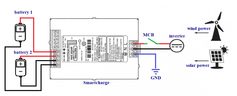
Solar panel RN200 can be used in parallel between renewable energy sources and generator sources to operate loads or generate on the grid, the energy types of renewable energy sources are usually solar power, wind energy, etc. RN200 allows to check the parameters of current, voltage, capacity,…. on the system to control the renewable energy system more easily.
Application of renewable energy source controllers used in solar and wind energy systems to generator synchronization renewable sources together for load use.
Currently TTTT Global we have Sices RN200 including user manual and product documentation. Contact our TTTT Global now to learn more about the SICES RN200 renewable energy source controller.
Company name:
TTTT GLOBAL co Ltd,.
Address: Landmark 4 Building, Vinhomes Central Park, 720A Dien Bien Phu Str, Ward 22, Binh Thanh District, Ho Chi Minh City, Vietnam.
Website: https://ttttglobal.com/en/
Hotline: +84286 2728 334
Email: Info@ttttglobal.com
CATEGORY: SICES DOCUMENTS
RELATED POSTS


 Tiếng Việt