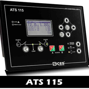
Sices ATS115 is used to handle automatic and manual switching between mains power and generator power. The ATS115 controls power transfer for 3-phase power supplies and monitors the voltage and power of mains and generators.
![Sices ATS115 Plus - [Made in Italy] ATS Controller Cổng ATS115](https://ttttglobal.com/wp-content/uploads/2022/04/Cong-ATS115-400x400.jpg)
| SICES CONTROLLER | INFORMATION |
| ORIGIN OF SICES ATS 115 | Italy |
| SICES ATS 115 Manual pdf | Download |
| APPLICATION OF SICES ATS 115 | The controller automatically transfers power for 3-phase voltage and monitors the voltage and power supply of mains and generators. |
| CONNECTION PORT OF SICES ATS 115 | RS232 (Plus Version) ,RS485(Plus version), Ethernet(Plus Version), USB |
Key information about the SICES ATS115 controller
- TTTT Global is currently a genuine Sices ATS controller representative.
- Sices ATS 115 Automatic Transfer Switch controller with 3 phase (RMS) mains voltage and 3 phase (RMS) generator voltage and current monitoring, suitable for operation with two different power sources.
- Sices ATS115 TTTT /ATS11 Plus is a device suitable to manage the switch in different plants configuration.
- A or B sources can be set as “mains” or “genset” in any possible combination.
- All the parameters can be set directly by the controller’s keyboard or, alternatively using the free software tool (BoardPRG3), available from SICES’ website.
- ATS115, in both versions, has a graphic display that allows a real time check of the switch status, of measures and any occurred alarms.
- ATS115 and ATS115 Plus allows the remote control of the switch by its communication ports.
- The plus version, have an extensive input and output capability with optional communication interfaces.
- On the TTTT Global site, there are not only Sices ATS 115 pdf but also Sices ATS 115 manual.
Sices ATS115 automatic power transfer controller
Main features
- True RMS measure for voltages of both sources, currents on loads.
- Measure of active power and power factor.
- Measure of frequency for both sources, powers on load.
- 8 programmable digital inputs (insulated).
- 8 programmable digital outputs.
- USB Port and ETHERNET Port (for ATS115Plus).
- Graphic display with single-line diagram representation.
- Real time clock.
- Events and data recording.
- Remote switch commands and remote start and stop commands.
- Embedded alarm horn.
![Sices ATS115 Plus - [Made in Italy] ATS Controller ATS controller](https://ttttglobal.com/wp-content/uploads/2022/04/retro_ats115-min-626x400.jpg)
Reference: Sices GC250
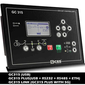
Reference: Sices GC315
Sices ATS 115 Specification
Connection port of Sices ATS 115
- 12 digital input ports.
- 12 digital output ports.
- 3 analog input ports.
- 1 analog output port.
- AND/OR logic control gate.
- USB N.1.
Connection port of Sices ATS 115 Plus
- 8 digital input ports.
- 8 digital output ports.
- 4 analog input ports.
- AND/OR logic control gate.
- USB port N.1.
- RS232 Modbus RTU serial port.RS485 Modbus RT isolated serial port.
- Ethernet port N.1 (RJ45) Modbus TCP/IP.
Other options
- GSM/GPRS/GPS modem (REWIND): SMS in case of alarm and alarm.
- PSTN modem for data calls in case of alarms and alarms.
- Monitoring software for Windows.
Functions that can be installed
- True RMS measure for voltages of both sources, currents on loads.
- Measure of active power and power factor.
- Measure of frequency for both sources, powers on load.
- 8 programmable digital inputs (insulated).
- 8 programmable digital outputs.
- USB Port and ETHERNET Port (for ATS115Plus).
- Graphic display with single-line diagram representation.
- Real time clock.
- Events and data recording.
- Remote switch commands and remote start and stop commands.
- Embedded alarm horn.
Status and signal
- Direct source A (Mains or Genset).
- Direct source B (Mains or Genset).
- Source A closes the circuit.
- Source B closes the circuit.
- Source A or B starts/stops.
- Remote start.
- Battery failure (max/min voltage).
- Emergency stop.
- Clock setting failed.
Methods of protection
- Genset “X” does not stop.
- Genset “X” is out of range.
- Source A or B does not achieve operation control.
- Source A or source B is out of phase order.
- Source A or source B is faulty.
- Source A or source B circuit breaker does not open.
- Source A or source B does not close the circuit.
A set of high-performance LEDs are used to signal generator states and potential alarms. Sub-alarms are indicated by their respective display codes.
Device information
- Supply voltage: 7 to 32 VDC.
- Power Consumption: Typically less than 2W (auto mode, standby mode, LCD lamp saving operation).
- Operating frequency 50Hz or 60Hz (AC read only).
- LCD with backlight.
- Operating temperature: -25oC to 60oC.
- Degree of protection: IP65 (including gasket).
- Weight: 600 gr – 650 gr (Plus version).
- Overall dimensions: Length 244 x Width 178 x Height 40 mm.
- Panel cut: Length 218 x Width 159 mm.
- Graphics display size: 70x38mm – 128×64 pixels.
- EMC: conforms to EN61326-1.
- Safety: Built in compliance with EN61010-1.
![Sices ATS115 Plus - [Made in Italy] ATS Controller Kết nối chân ATS 115](https://ttttglobal.com/wp-content/uploads/2022/04/ATS-115-min-557x400.jpg)
If you need more information about Sices generator protection relay and automatic transfer switch for generator
TTTT GLOBAL co Ltd,.
Address: Landmark 4 Building, Vinhomes Central Park, 720A Dien Bien Phu Str, Ward 22, Binh Thanh District, Ho Chi Minh City, Vietnam.
Website: https://ttttglobal.com/en/
Hotline: +84286 2728 334
Email: Info@ttttglobal.com


 Tiếng Việt
![Sices BTB200 - [Italy] Bus tie breaker, Busbar electrical panel controller Sices BTB200](https://ttttglobal.com/wp-content/uploads/2022/08/Sices-BTB-100x100.jpg)
![Sices GC250 controller [Made in Italy] sices-gc250](https://ttttglobal.com/wp-content/uploads/2022/04/sices-gc250-100x100.jpg)
![Sices ATS115 Plus - [Made in Italy] ATS Controller sices-ats115](https://ttttglobal.com/wp-content/uploads/2022/04/sices-ats115.jpg)
![Sices ATS115 Plus - [Made in Italy] ATS Controller ATS controller](https://ttttglobal.com/wp-content/uploads/2022/04/retro_ats115-min.jpg)
![Sices ATS115 Plus - [Made in Italy] ATS Controller ATS controller](https://ttttglobal.com/wp-content/uploads/2022/04/retro_ats115-min-300x300.jpg)
![Sices ATS115 Plus - [Made in Italy] ATS Controller Báo giá](https://ttttglobal.com/wp-content/uploads/2022/04/Bao-gia-3.png)
